Ekeberg Prize 2023 - Winner
Tailoring Nb-based alloys for Additive Manufacturing: From powder production to parameter optimization
Tailoring a speciality alloy for Additive Manufacturing - From powder production to parameter optimization
Dr. Markus Weinmann (TANIOBIS GmbH), Shaumik Lenka (Alloyed), Dr. André Németh (TANIOBIS GmbH), Dr. Melanie Stenzel (TANIOBIS GmbH)
Motivation
Ultra-high temperature refractory alloys have the potential to perform at temperatures exceeding ~1050 °C, outperforming even the most advanced Ni- and Co-based superalloys due to their ceiling imposed by the strengthening phase stability as well as their high melting point. Niobium-based alloys, such as C-103, are of particularly interest due to relatively low density, good thermal conductivity and excellent temperature & time-dependent mechanical properties (Fig. 1). [1],[2]

Fig. 1: Creep performance of various high temperature alloys showing the superiority of Nb alloys. Data for superalloys extracted from Ref. [3]
As a result, Niobium-base alloys are commonly used in propulsion systems within the space and defense industry. [4] Typical applications have until recently been limited to simple shapes such as products made from sheet and bar such as expansion chamber skirts made from TIG welded sheet. This is as ingot production is expensive and they are challenging to fabricate into complex shapes due to their high hot working temperature. Because of the high cost of manufacture not the strongest but most readily manufacturable alloy C-103 is left in the market today.
Until now near net-shape manufacture was not possible as investment casting has challenges around mold reactions, insufficient superheating as well as economic reasons such as loss of the alloy in gates. [5] Processing these unique high temperature alloys in powder form allows for near-net shape manufacture using laser powder bed fusion (L-PBF), electron beam powder bed fusion (EB-PBF), direct energy deposition (DED), [6] as well as advanced powder metallurgy (PM). These technologies have major advantages over conventional processing such as cheaper part production due to more efficient use of material and the ability to produce complex components.
The ability to manufacture complex shapes from C-103 [7] and FS-85 (here described for the first time) via L-PBF enables new applications such as structures for high velocity flight and re-entry guidance but also to enable higher temperature gas turbines for power generation and jet propulsion.
Alloy powder preparation
Niobium-base C-103 and FS-85 alloy powders have been developed at TANIOBIS GmbH, Germany, and are commercially available as AMtrinsic® C-103 or AMtrinsic® FS-85 [8] pre-alloyed powders. Due to the lack of suitable crucible materials they are atomized by electrode induction-melting gas atomization (EIGA) [9] of pre-alloyed electrodes. The electrodes were electron beam-melted with dimensions of ca. d x l = 45 mm x 650 mm. Prior to their use a 90° tip was machined to fit shape and dimension of the induction coil. The pre-alloyed rods were atomized in a purified Ar (4.6, Linde) atmosphere through a Laval nozzle and the as-obtained raw powders sifted to remove the fine powder fraction < 10 µm. Finally, the sifted powders were fractionized through 63 µm, 105 µm and 150 µm meshes. The classification releases powders with particle size distributions typically applied in L-PBF (10 – 63 µm), EB-PBF (63 – 105 µm) or in DED (105 – 150 µm).
Alloy powder characterization
Niobium-base C-103 and FS-85 L-PBF alloy powders have fully been characterized, chemically by a combination of ICP-OES and carrier gas hot extraction and/or combustion analysis as well as morphologically by XRD and SEM/EDX. Their flowability was investigated using Hall Flow measurements.
The chemical composition of C-103 and FS-85 powders determined spectroscopically (ICP-OES) and by carrier gas hot extraction/combustion analysis is provided in Table 1. For comparison, the overall composition and the composition of selected spots determined by EDX are given.
|
|
(wt%) |
(ppm) |
|||||||||
|
alloy |
Analysis |
Nb |
Ta |
Hf |
W |
Ti |
Zr |
C |
H |
N |
O |
|
C-103 |
Chemical |
88.7 |
0.2 |
9.6 |
< 0.1 |
1.0 |
0.2 |
29 |
< 10 |
44 |
198 |
|
EDX aera |
89.2 |
-- |
9.7 |
-- |
0.1 |
1.0 |
0 1) |
-- |
-- |
0 1) |
|
|
EDX spot 1 |
90.5 |
-- |
8.5 |
-- |
0.0 |
1.1 |
0 1) |
-- |
-- |
0 1) |
|
|
EDX spot 2 |
79.2 |
-- |
19.6 |
-- |
0.1 |
-- |
0 1) |
-- |
-- |
0 1) |
|
|
FS-85 |
Chemical |
60.8 |
28.3 |
0.03 |
10.0 |
0.01 |
1.0 |
< 10 |
< 10 |
19 |
289 |
|
EDX aera |
61.7 |
26.3 |
-- |
9.8 |
-- |
2.3 |
0 1) |
-- |
-- |
0 1) |
|
|
EDX spot 1 |
68.2 |
21.1 |
-- |
5.8 |
-- |
4.9 |
0 1) |
-- |
-- |
0 1) |
|
|
EDX spot 2 |
58.3 |
29.3 |
-- |
10.4 |
-- |
1.9 |
0 1) |
-- |
-- |
0 1) |
|
|
1)below detection limit |
|||||||||||
|
-- not determined |
|||||||||||
The chemical compositions of the atomized powders correspond well with those of conventionally processed materials. However, due to the much higher surface areas, the contents of the light elements, i.e. C, N and O are slightly higher than in the cast solids.
Investigations by XRD shown in Fig. 2 point to the fact that C-103 and FS-85 alloy powders crystallized in the body-centered cubic crystal structure. A comparison with pure Nb shows the very similar appearance of the XRD patterns with the typical 110, 200 and 211 ß-phase reflections. Accordingly, C-103 as well as FS-85 can be considered as single-phase materials.

Fig. 2 XRD pattern of C-103 and FS-85 alloy powders and comparison with pure Nb powder

Fig. 3 SEM images of C-103 and FS-85 alloy powders recorded at 100x magnification
For application in powder bed additive manufacturing processes a good processability of the powder is mandatory. [10] A spherical shape is one important requirement to guarantee free flow and ensure a homogeneous distribution of the powder in each individual coating step. Other prerequisites are the absence of satellites, i.e. attachment of smaller particles on the surface of bigger particles or agglomerates. The absence of pores or voids in the powders is necessary to avoid the inclusion of porosity in the built part.
Both C-103 and FS-85 L-PBF powders show an ideally spherical microstructure, as can be seen from the SEM images in Fig. 3. They have smooth surfaces and are fully deagglomerated. In addition, satellites are absent and consequently the powders possess very appreciable flow properties. Their Hall Flow according to ASTM B213 is 12 s (C-103) and 8 s (FS-85). Particle size measurements by means of laser diffraction indicates narrow distributions with d50 values of 34 µm and 39 µm. Tap densities are in the range of 5.5 g/cm3 (C-103) and 6.5 g/cm3 (FS-85). The higher density of FS-85 is attributed to its substantial amounts of Ta and W.

Fig. 4 BSE images of polished cross sections of C-103 and FS-85 alloy powders recorded at 2500x magnification
From the polished cross-sections shown in Fig. 4 it can be concluded that the particles are fully dense. Voids, defects or inhomogeneities are not observed. Interestingly, the BSE images of both C-103 and FS-85 show structural features with a more or less pronounced dendritic appearance. Similar observations have been made for Nb and Ta-modified Ti base alloys. [11] In C-103 they do not appear clearly, while the BSE image from FS-85 undoubtedly shows flower-like dendritic features. In addition, the contrast in the image of FS-85 is significantly higher than that of C-103.
The EDX images of C-103 and FS-85 provided in Fig. 5 show clear differences in the distribution of the elements. In C-103, chemical variation of the main components Nb and Hf is observed. Nb appears enriched in the dendritic phase while Hf is enriched in the inter-dendritic phase. This is clearly expressed by the different chemical compositions, which are highlighted in Table 1 of spots 1 and 2 in the Hf map of C-103. While the dendrite-type features contain 90.5 wt% Nb and 8.5 wt% Hf, the volumes between the dendrites consist of 79.2 wt% Nb and 19.6 wt% Hf. The secondary components Ti and Zr appear homogeneously distributed over the particle.
The element distribution in FS-85 is very different. None of the elements appears homogeneously distributed throughout the particles. There is a clear separation into Nb/Zr and Ta/W enriched volumes. In contrast to C-103, Nb appears with higher concentration in the inter-dendritic phase associated with Zr. In contrast, Ta and W occur preferentially in the dendrite phase. The chemical fluctuations of the elements in both phases are significantly more pronounced than with C-103. While spot 1, which indicates the composition of the inter-dendrite phase, consists of 68.2 wt% Nb, 21.1 wt% Ta, 5.8 wt% W and 4.9 wt% Zr, respectively the values ​​in the dendritic structures (cf. spot 2) are 58.3 wt%, 29.3 wt%, 10.4 wt% and 1.9 wt%.


Fig. 5 EDX images of polished cross sections of C-103 (top) and FS-85 (bottom) alloy powders recorded at 2500x magnification. The chemical composition of the entire are and selected spots 1 and 2 is provided in Tab. 1
C-103 and FS-85 powder particles were also investigated by means of Electron Backscatter Diffraction (EBSD) to receive information of crystal size, structure and orientation. Powder samples were therefore hot mounted by mixing with a conductive mount and subsequently mechanically polished using 600-4000 abrasive grit papers. The polishing was then continued using diamond paste from 10 to 1 µm to have a mirror finish and finally finishing the polishing with 0.25 µm colloidal silica solution to get surface conducive for electron backscattered diffraction scans. The high angle boundaries in these images are the boundaries between two different grains and the low angle grain boundaries are the inter-dendritic boundaries within the same grain.


Fig. 6 EBSD of C-103 (left) and FS-85 (right) powders showing the grain structure within the powder particles.
The average grain size of C-103 particles, which measures up to approx. 20 µm appears to be sligthly higher than in FS-85. This might be a consequence of the higher number of constituents in FS-85 than in C-103 and consequently a higher entropy of the FS-85 system, exhibiting extensive crystallization. Such effect is well known for refractory metal high entropy alloys, which have recently been discribed in the literature.
Method of manufacture (Alloyed process for parameter development)
The additive manufacturability of C-103 and FS-85 has been assessed by laser powder bed fusion (L-PBF) in a protective argon atmosphere using a Renishaw AM400 (Fig. 7) pulsed fiber laser system with 1075 nm wavelength. Printing any new alloy or composition requires single track experiments (Fig. 8) to be done at the various additive manufacturing machine settings to get the information about melt-pool thickness and depth. This is key to make sure the melt-pools overlap creating sound builds without any remnant unfused powder. Single track also helps parameter selection by adjusting the tradeoff between a stable scan track and keyhole formation due to high enthalpy. Fig. 8 provides a schematic of the various AM machine parameters that have been tested. A snapshot of the single track samples has also been shown in Fig. 8 which were metallographically analyzed to determine scan track stability and soundness.

Fig. 7 Renishaw AM 400 machine used at Alloyed Inc to build cubes and test bars in a reduced build volume.


Fig. 8 Single track DOE (top) and experiments (bottom) conducted in Renishaw AM 400 machine at 300-400 W with 50-90 µs exposure time and 10-50 µm point distance.
The scan track width and 1 dimension energy density were plotted along with the ranking of the tracks based on the stability post metallographic analyses. This is shown in Fig. 9 and can then be used as a map to visualize effect of operating parameters on printability.

Fig. 9 Process parameter and microstructure stability plot generated by characterizing single tracks made from various operating conditions for FS-85.
The AMtrinsic® C-103 and FS-85 powders after being thoroughly characterized as described in Section 1 were printed with varied process parameters according to the design of experiment strategy. Cubes of the dimension of 10x10x10 mm3 were manufactured with varying processing parameters as shown in Table 1 at a fixed layer thickness of 30 µm. A meander laser scan path was applied with a rotation of 67 deg with each layer.
Table 1: Range of parameters used for design of experiment to determine the printability of FS-85 and C-103 alloys.
|
Parameter |
Range |
|
Laser power |
200 W and 300 W |
|
Exposure time |
70 µs |
|
Hatch distance |
70 µm to 110 µm in steps of 10 µm |
|
Point distance |
30 µm, 40 µm, 50 µm and 70 µm |
Fig. 10 shows a snapshot of one particular DOE strategy of 12 cubes being printed. Once the optimized process parameter was narrowed down, a full test bar build was done as shown in Fig. 10. Post printing of the cubes a full microstructural characterization was done to correlate the process parameters and microstructural attributes. The density of the cubes and the AM defects concentration (cracks and porosities measured through microstructural characterization) were correlated with the build parameters such as laser power, exposure time, hatch and point distance.
.jpg)


Fig. 10 Cube build of C-103 and FS-85 (top) as a part of the design of experiment strategy. Full test bar build (bottom) with the optimized printing parameters.
The influence of the processing parameters such as laser power, scan speed, hatch, powder bed thickness etc. on the quality of the print can be assessed by investigating its density/porosity. It can be seen that as the laser power (all other parameters remain unchanged) is lowered from 300 W to 200 W defects or pores around the corners, borders and bulk are significantly reduced.


Fig 11. Optical micrograph of DOE cubes processed at 300W (left) and 200W (right) showing significant difference in defect concentration, size and shape.
Characterization of additive manufacturability (Comparison of density of C-103 and FS-85)
Cubes with density ≥ 99.9 % were obtained applying optimized processing parameters. The comparison of corners, borders and bulk microstructure has been done and the micrographs for C-103 and FS-85 have been shown in Fig. 12 and Fig. 13, respectively. It can be seen that both alloys are readily processable through laser powder bed fusion.


Fig 12. Optical micrograph of corner (left), bulk (middle) and border (right) micrographs showing feeble presence of defects/porosities for C-103 cube build with optimized parameters.


Fig 13. Optical micrograph of corner (left), bulk (middle) and border (right) micrographs showing feeble presence of defects/porosities for FS-85 cube build with optimized parameters.
Characterization of additive manufacturability (Advanced chemical and micro characterization / EBSD)
Additive manufacturing using selective laser beam melting has a significant impact on the development of the morphology of the materials used. This can be seen exemplarily for FS-85 by comparing the powder morphology shown in Fig. 5 with that of the L-PBF-printed material shown in Fig. 14.

Fig. 14 EDX images of polished cross sections of FS-85 printed specimens recorded at 3000x magnification. Build direction from right to left. The dashed line in the W map highlights melt pool boundaries along which a slight de-mixing occurs.
During the impact of the laser beam on the powder bed, it melts completely. Moreover, the underlying layers are also melted and accordingly each individual layer is therefore remelted several times in the process. In the molten layers, the individual atoms are randomly distributed, with maximum disorder; they exhibit a maximum entropy. Since the cooling rates for L-PBF are extremely high at around 105 K/min, a thermodynamically favored partial de-mixing with the formation of dendrite-like structures observed in the powder particles can no longer take place. The remaining structure therefore has a very high entropy and random element distribution.
At the deepest part of the melt pool, i.e. at the solid/liquid boundary, a slight segregation of the alloy may occur. The reason is that the individual alloy components solidify with different rates which causes the segregation. Two such melt pool boundaries are indicated in Fig. 5 in the tungsten map by a dashed line. The melt pool boundaries are likewise visible, though not highlighted, in the Nb, Ta and Zr map.
To make sure all printed components fulfill the composition specification for C-103 and FS-85 standards, advanced chemical analysis such as ICP and LECO were done. Table 2 shows the oxygen concentration measured using LECO for powders and the components made through additive manufacturing. This level of quality check is required for stringent qualification of various classes of components for space applications. In general, a slight increase of oxygen caused by the L-PBF processing of 140 – 250 ppm is observed.
Table 2. Oxygen content of powders and additively manufactured components measures through LECO for qualification and understanding the oxygen pickup during printing.
|
Alloy |
Source |
Process |
Oxygen content / ppm |
|
|
Powder |
AM coupon |
|||
|
FS-85 |
Alloyed/Taniobis |
SLM |
180 |
398 |
|
C-103 |
Alloyed/Taniobis |
SLM |
248 |
423 |
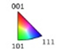
Advanced electron back scattered diffraction examination of the AM printed parts were done to see the grain structure in the as-printed components. EBSD map of C-103 and FS-85 (Fig.15) shows predominant (101) and (111) texture, respectively. This change in texture from cube on the edge to cube on the corner dependence could be attributed to the difference in chemical composition leading to a difference in solidification texture during printing of powders using L-PBF.


.jpg)
Fig 15. EBSD of C-103 (left) and FS-85 (right) as-printed parts
Mechanical Performance (room temperature tensile performance)
Mechanical performance of the additively manufactured FS-85 and C-103 at room temperature was measured using standard ASTM E8 tests. Rectangular blanks of dimension 55x10x10 mm3 were machined into cylindrical dumbbell specimen with threads on either end. The samples were tested in tension in a 30 kN Intron tensile testing machine at a strain rate of 0.005 mm/min. Figure 16 shows the room temperature performance of additively manufactured FS-85 and C-103.

Fig. 16 Mechanical properties of C-103 and FS-85 alloys at room temperature processed by L-PBF.
It is found that FS-85 is significantly stronger than C-103. The corresponding ultimate strengths are ca. 750 MPa and 565 MPa, respectively. On the other hand, C-103 exhibits a significantly higher strain-to-failure of ca. 20 – 22 % compared with ca. 6 – 7 % in FS-85. Both alloys are currently being mechanically tested at higher temperatures up to 1500°C to evaluate their potential for service in high temperature environments. [13]
As evident from Fig. 17, an excellent high-temperature performance can be observed for both alloys at elevated temperature. Either of the alloys produced by PBF-LB clearly outperforms wrought C-103 in terms of strength and density-compensated strength. In accordance with room temperature investigations, the tantalum-modified FS-85 alloy is the first choice when searching for new alloys for service in high-temperature environments.

Fig. 17 Yield strength obtained in high-temperature tensile tests (ETMT) of PBF-LB-processed C-103 and FS-85.
Outlook, component manufacture
C-103 and tantalum-containing FS-85 alloys prove to have superior printability and mechanical properties comparable to the conventionally processed alloys. These alloys therefore need to be manufactured into prototype components to prove the validity of these alloys in actual component manufacture for space applications. Fig 18 shows such a particular prototype thruster manufactured using FS-85 alloy processed by laser powder bed fusion.


Fig. 18 Thrusters component printed out of FS-85 alloy to showcase the prototype component manufacture
[1]V. V. Satya Prasad, R. G. Baligidad, Amol A. Gokhale, Niobium and Other High Temperature Refractory Metals for Aerospace Applications in Aerospace Materials and Material Technologies, Springer Singapore (2017), Eds. N. Eswara Prasad, R. J. H. Wanhill
[2]N. Philips, M. Carl, N.J. Cunningham, New Opportunities in Refractory Alloys, Metallurgical and Materials Transactions 51A (2020) 3301
[3]J. Hakl, T. Vlasák, J. Lapin , Creep behaviour and microstructural stability of cast nickel based superalloy IN 792 5A, Kovove Mater. 45 (2007) 177–188
[4]J. J. Stephens, Recent advances in high-temperature niobium alloys, JOM 42 (1990) 22–23
[5]K. Chattopadhyay, R. Goswami, Melting and Superheating of Metals and Alloys, Prog. Mater. Sci. 42 (1997) 287-300
[6][6]See for example C. Aumund-Kopp, A. Riou, Introduction of Additive Manufacturing Technology, European Powder Metallurgy Association 2015, 1st Edition
[7]O.R. Mireles, O. Rodriguez, Y. Gao, N. Philips, Additive Manufacture of Refractory Alloy C103 for Propulsion Applications, AIAA Propulsion and Energy 2020 Forum, August 24-28, 2020, VIRTUAL EVENT
[8]AMtrinsic® is a registered trademark of TANIOBIS GmbH
[9]S. Pleier, W. Goy, B. Schaub, M. Hohmann, M. Mede, R. Schumann, EIGA-Innovative Production Method for Metal Powder from Reactive and Refractory Alloys, in Powder metallurgy & particulate materials; proceedings of the international conference on powder metallurgy & particulate materials 2-49-2-55 (2004)
[10]D. Huck-Jones, C. Langley, Beyond particle size: Exploring the influence of particle shape on metal powder performance, Metal Additive Manufacturing 3(4) (2017) 99-103
[11]C. Schulze, M. Weinmann, C. Schweigel, O. Keßler, R. Bader, Mechanical Properties of a Newly Additive Manufactured Implant Material Based on Ti-42Nb, Materials 11 (2018) 124
[13]S. Lenka et al., in preparation for publication


